
Still trying to figure out my fueling problem.
I think the bus gave me some clues, but I'm trying to piece them together. She always started within about 2 cranks, about 1 second at the most. For 2 days before she wouldn't start she took 5-10 cranks. With no power to the fuel pump I have to depress the gas pedal to allow more air for the bus to start, and I can rev it all the way up without any lean cutting out. Do I have a torn/punctured fuel pump diaphragm? If there is power to the pump it floods out too much to even start.
76 FI 2.0
76 Bus Fuel Injection Troubleshooting- It Runs 8/13/07
-
NWbuspilot
- Getting Hooked!
- Location: Monmouth, Oregon
- Status: Offline
-
soulful66

- Addicted!
- Status: Offline
Your fuel pump does not have a diaphram. It is an electric pump. The bentley manual has the testing procedures for you.
You can test the pressure and volume of the pump by turning the key on and moving the wiper in the AFM to closed the fuel pump contact. Be Sure to have a suitable container to catch the fuel in when doing the volume test.
High fuel pressure can cause the flooding. The pressure regulator most likely is the culprit. Test every fuel system component first before swapping out parts. These parts are expensive, and the troubleshooting of my own bus' fuel problems gave me alot of understanding of how it works.
Best Regards,
John
'72 westy 3TC
'73 westy 1700 dual solex
'79 westy 2000 F.I.
'73 westy 1700 dual solex
'79 westy 2000 F.I.
-
NWbuspilot
- Getting Hooked!
- Location: Monmouth, Oregon
- Status: Offline
Thanks. I have already replaced the fuel pressure regulator, as well as the line behind it. I did some more testing today and found out that my fuel injectors are getting power as soon as the key comes on, and are remaining fully powered while the starter is cranking as well.
I haven't been able to get access to a bentley manual yet. I was hoping to pick one up at the Portland Bug In but didnt have any luck finding one.
I haven't been able to get access to a bentley manual yet. I was hoping to pick one up at the Portland Bug In but didnt have any luck finding one.
-
Amskeptic

- IAC "Help Desk"

- Status: Offline
As they should.NWbuspilot wrote:Thanks. I have already replaced the fuel pressure regulator, as well as the line behind it. I did some more testing today and found out that my fuel injectors are getting power as soon as the key comes on, and are remaining fully powered while the starter is cranking as well.
You are supposed to have an energized fuel pump during cranking also.
The injectors are pulse grounded at the ECU based on a signal from the coil #1 terminal (little white wire).
See if it pulses during cranking. If no, clean and gap breaker points carefully.
If yes, please check all grounds and . . . hey John! should we tell him to check the ecu terminals to make sure they are all sticking out the same amount?
Colin
BobD - 78 Bus . . . 112,730 miles
Chloe - 70 bus . . . 217,593 miles
Naranja - 77 Westy . . . 142,970 miles
Pluck - 1973 Squareback . . . . . . 55,600 miles
Alexus - 91 Lexus LS400 . . . 96,675 miles
Chloe - 70 bus . . . 217,593 miles
Naranja - 77 Westy . . . 142,970 miles
Pluck - 1973 Squareback . . . . . . 55,600 miles
Alexus - 91 Lexus LS400 . . . 96,675 miles
-
NWbuspilot
- Getting Hooked!
- Location: Monmouth, Oregon
- Status: Offline
-
Amskeptic
- IAC "Help Desk"
- Status: Offline
Careful with your terminology here, young budding mechanic.NWbuspilot wrote: During cranking it doesn't pulse either. I am grounding the test light at the body, do I need to ground it at the negative terminal of the coil?
We are not "grounding" the test light at #1 terminal on the coil even if it has a (-) marking. We are putting the test prong on #1 (-) and grounding the alligator clip of the test lamp to the body of the car. Then we get to "see" the electrical path INTERRUPT in concert with the breaker points inside of the distributor. The breaker points INTERRUPT the circuit through the coil, the circuit that comes in at #15(+) and leaves at #1(-) to go to the distributor through the *(green usually) wire that terminates at the points. The points are where the circuit gets grounded then interrupted (the points interrupt the circuit which triggers the coil to unleash a mighty 20,000 volt spark to the plugs via the rotor and cap atop the distributor). The ECU is merely reading the circuit interruptions like your test lamp does. Then the ECU decides to ground the injectors briefly to spray fuel into the intakes based on the signal from the white wire that is attached to #1 (-) at the coil. If your injectors are all grounding all the time, you will have serious flooding and fuel smell. That would be a unique horror that has an easy or horrendously difficult solution. You would have to pull the injectors, disable the ignition system if you want to live, and turn on the ignition to see if the injectors spray. If they do, either the ECU is toast or there is the first short-to-ground for all injector wires ever recorded in human history, and I ain't saying it ain't possible.
They are inside the distributor. Get thee a John Muir manual and a Bentley and read your way into it.NWbuspilot wrote: Also, how exactly do I clean and gap the breaker points? And where are they?
Colin
BobD - 78 Bus . . . 112,730 miles
Chloe - 70 bus . . . 217,593 miles
Naranja - 77 Westy . . . 142,970 miles
Pluck - 1973 Squareback . . . . . . 55,600 miles
Alexus - 91 Lexus LS400 . . . 96,675 miles
Chloe - 70 bus . . . 217,593 miles
Naranja - 77 Westy . . . 142,970 miles
Pluck - 1973 Squareback . . . . . . 55,600 miles
Alexus - 91 Lexus LS400 . . . 96,675 miles
-
soulful66
- Addicted!
- Status: Offline
Na, let's apply a sadistic, but helpful, month long troubleshooting of the F.I. system. It was a real good way for me to get to the bus' wiring and component workings. OK FINE! Check the ECU pins!Amskeptic wrote:[ . . . hey John! should we tell him to check the ecu terminals to make sure they are all sticking out the same amount?
Colin
All kidding aside, do not be afraid to remove the F.I. wiring harness and do continunity checks of it's wires. The harnesses are very old and the heat thet endure makes them brittle wick can easily cause a wire to break inside the loom. The F.I. harness can be removed with the engine in, and really check all of the rubber parts for cracks.(vacuum leaks)
Use the Bentley test procedures. They really helped me and it will save alot of money over swapping parts out. Hang in there, you will provail!!
Best Regards,
John
'72 westy 3TC
'73 westy 1700 dual solex
'79 westy 2000 F.I.
'73 westy 1700 dual solex
'79 westy 2000 F.I.
-
NWbuspilot
- Getting Hooked!
- Location: Monmouth, Oregon
- Status: Offline
Amskeptic wrote:Careful with your terminology here, young budding mechanic.NWbuspilot wrote: During cranking it doesn't pulse either. I am grounding the test light at the body, do I need to ground it at the negative terminal of the coil?
We are not "grounding" the test light at #1 terminal on the coil even if it has a (-) marking. We are putting the test prong on #1 (-) and grounding the alligator clip of the test lamp to the body of the car. Then we get to "see" the electrical path INTERRUPT in concert with the breaker points inside of the distributor. The breaker points INTERRUPT the circuit through the coil, the circuit that comes in at #15(+) and leaves at #1(-) to go to the distributor through the *(green usually) wire that terminates at the points. The points are where the circuit gets grounded then interrupted (the points interrupt the circuit which triggers the coil to unleash a mighty 20,000 volt spark to the plugs via the rotor and cap atop the distributor). The ECU is merely reading the circuit interruptions like your test lamp does. Then the ECU decides to ground the injectors briefly to spray fuel into the intakes based on the signal from the white wire that is attached to #1 (-) at the coil. If your injectors are all grounding all the time, you will have serious flooding and fuel smell. That would be a unique horror that has an easy or horrendously difficult solution. You would have to pull the injectors, disable the ignition system if you want to live, and turn on the ignition to see if the injectors spray. If they do, either the ECU is toast or there is the first short-to-ground for all injector wires ever recorded in human history, and I ain't saying it ain't possible.
They are inside the distributor. Get thee a John Muir manual and a Bentley and read your way into it.NWbuspilot wrote: Also, how exactly do I clean and gap the breaker points? And where are they?
Colin
Ok- breaker points are the points
Connecting the test lamp to the negative terminal on the coil makes more sense. If I understand it correctly, this will provide an intermittent ground to the body when the breaker points close. So, In theory, if my points are opening and closing correctly the problem would lie in either the ECU or the harness?
-
NWbuspilot
- Getting Hooked!
- Location: Monmouth, Oregon
- Status: Offline
I think I'm in for some continuity testing on Sunday. I'm thinking it may be a broken/shorted wire- the problem occurred suddenly, as in the bus drove and ran like a top when it was parked around 11pm, then refused to fire up at 8am the next morning.soulful66 wrote:Na, let's apply a sadistic, but helpful, month long troubleshooting of the F.I. system. It was a real good way for me to get to the bus' wiring and component workings. OK FINE! Check the ECU pins!Amskeptic wrote:[ . . . hey John! should we tell him to check the ecu terminals to make sure they are all sticking out the same amount?
Colin
All kidding aside, do not be afraid to remove the F.I. wiring harness and do continunity checks of it's wires. The harnesses are very old and the heat thet endure makes them brittle wick can easily cause a wire to break inside the loom. The F.I. harness can be removed with the engine in, and really check all of the rubber parts for cracks.(vacuum leaks)
Use the Bentley test procedures. They really helped me and it will save alot of money over swapping parts out. Hang in there, you will provail!!
Best Regards,
John
On a sidenote- the lifters are ticking like crazy due to the gas that washed down the cylinders from all the flooding. Now that I have changed the oil and filter can I expect them to pump back up after being run for a while?
-
NWbuspilot
- Getting Hooked!
- Location: Monmouth, Oregon
- Status: Offline
Another quick question- Does anyone have photos of what my ECU pins should look like?
And also can someone do a quick write up of the pins on the FI harness and what they are connected to for continuity testing? I'm trying to locate a Bentley so I can have this info on hand, but I'm most likely going to have to order one online and probably won't see it by Sunday. I usually work all day everyday but Sunday.
Edit- I've been on a researching binge for the last while and was able to find this much out so far for testing the rest of the system.
AFM- should switch from infinite resistance to zero resistance between terminals 36 and 39 when the flap is opened.
Throttle valve should have full continuity between 2 and 18.
Temp Sensor should read 2k-3k ohms between 13 and 17 at 68 degrees.
Fuel Injectors should have 2-3 ohms between the 2 terminals.
If I end up having to cut off the heatshroud from the FI harness to visually trace each wire, would something like this work to cover the harness?
http://www.radioshack.com/product/index ... age=search
-
NWbuspilot
- Getting Hooked!
- Location: Monmouth, Oregon
- Status: Offline
I've now started my barrage of tests on the fuel injection system. Today after work I was able to test the Air Flow Meter and the injectors.
Here are my results- Everything I checked today tested within specs.
Air Flow Meter Resistance between Terminals-
6 and 9: 204 ohms
6 and 8: 204 ohms
8 and 9: 115 ohms
6 and 7: 52 ohms
7 and 8: 167 ohms
Fuel Injector Resistance Between Terminals:
Cylinder 1: 2.8 ohms
Cylinder 2: 2.9 ohms
Cylinder 3: 3.0 ohms
Cylinder 4: 3.0 ohms
When connecting the test light probe to the positive terminal on the fuel injector harness and the alligator clip to the negative terminal of the ignition coil all 4 pulsed when the starter was applied.
I have already tried bypassing the cold start valve with a length of fuel line, as I suspected it may be leaking. This didn't fix the problem.
I think my next checks will be the Temperature sensor resistance, the Thermotime switch, and going through the whole list of resistance checks for the FI harness in the AFC manual that I found online.
Sunday is reserved for these tests, as well as removing and thoroughly inspecting and replacing all of the bad vacuum lines. If everything is going well after that and she is up and running, Monday is set aside for replacing the fuel lines I haven't gotten to already, and fuel injector seals.
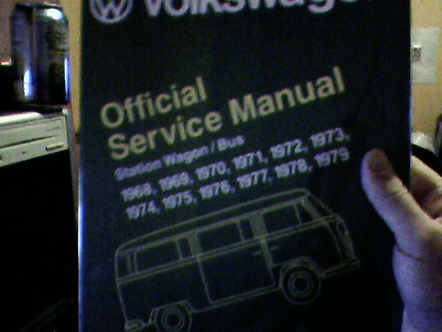
I was also able to have my wife pick this up for me while she was in town today:
Here are my results- Everything I checked today tested within specs.
Air Flow Meter Resistance between Terminals-
6 and 9: 204 ohms
6 and 8: 204 ohms
8 and 9: 115 ohms
6 and 7: 52 ohms
7 and 8: 167 ohms
Fuel Injector Resistance Between Terminals:
Cylinder 1: 2.8 ohms
Cylinder 2: 2.9 ohms
Cylinder 3: 3.0 ohms
Cylinder 4: 3.0 ohms
When connecting the test light probe to the positive terminal on the fuel injector harness and the alligator clip to the negative terminal of the ignition coil all 4 pulsed when the starter was applied.
I have already tried bypassing the cold start valve with a length of fuel line, as I suspected it may be leaking. This didn't fix the problem.
I think my next checks will be the Temperature sensor resistance, the Thermotime switch, and going through the whole list of resistance checks for the FI harness in the AFC manual that I found online.
Sunday is reserved for these tests, as well as removing and thoroughly inspecting and replacing all of the bad vacuum lines. If everything is going well after that and she is up and running, Monday is set aside for replacing the fuel lines I haven't gotten to already, and fuel injector seals.
I was also able to have my wife pick this up for me while she was in town today:
-
soulful66
- Addicted!
- Status: Offline
You do not want to ground the alligator clip to the negitive side of the ignition coil. Ground it to the body of the bus. Since the neg side of the coil will give the pulse reference to the ecu, you are getting a false reading. The blinking you are seeing is the input signal going to the ecu. By grounding to the body, you will be able to see if the ecu output signal is grounding the injectors, like it should.NWbuspilot wrote: When connecting the test light probe to the positive terminal on the fuel injector harness and the alligator clip to the negative terminal of the ignition coil all 4 pulsed when the starter was applied.]
Best Regards,
John
'72 westy 3TC
'73 westy 1700 dual solex
'79 westy 2000 F.I.
'73 westy 1700 dual solex
'79 westy 2000 F.I.
-
NWbuspilot
- Getting Hooked!
- Location: Monmouth, Oregon
- Status: Offline
I'm not sure if I follow that. Looking at the wiring diagram makes it look like grounding the test light at the body would essentially short the circuit.soulful66 wrote:You do not want to ground the alligator clip to the negitive side of the ignition coil. Ground it to the body of the bus. Since the neg side of the coil will give the pulse reference to the ecu, you are getting a false reading. The blinking you are seeing is the input signal going to the ecu. By grounding to the body, you will be able to see if the ecu output signal is grounding the injectors, like it should.NWbuspilot wrote: When connecting the test light probe to the positive terminal on the fuel injector harness and the alligator clip to the negative terminal of the ignition coil all 4 pulsed when the starter was applied.]
Best Regards,
John
Maybe a test light between the positive and negative terminals on the injector harness would serve best- and if it flashes we know the ECU output is good as well?
-
Randy in Maine

- IAC Addict!
- Location: Old Orchard Beach, Maine
- Status: Offline
-
NWbuspilot
- Getting Hooked!
- Location: Monmouth, Oregon
- Status: Offline
I've printed that one out, along with another AFC manual I found. I can't for the life of me remember the site I got the other manual from though. That page was great when I found it.Randy in Maine wrote:Just a sidenote...
I assume that you have this link http://manuals.type4.org/ljet/
With the L Jet manual, the AFC manual, Muir's Guide, advise from everyone at IAC, my $40 Bentley manual, and my useless Haynes manual I'd better be able to get this thing up and running again!