Sliding Door Latch Refresh (late)
Posted: Fri Jan 21, 2011 9:18 pm
Do you have a difficult-to-move handle on your post '73 bus?
Did you know that the resistance you experience is actually a coiled-up spring installed precisely to give you thatr resistance? Who wudda thunk?
Step 1) Remove Door Panel.
Start at a healthy section and pull out as close to a determined clip location as possible.
Before proceeding, please re-glue the entire perimeter of the vinyl to the masonite panel. I'll wait here . . . . .
Step 2) Release Cable and Return Spring Anchor
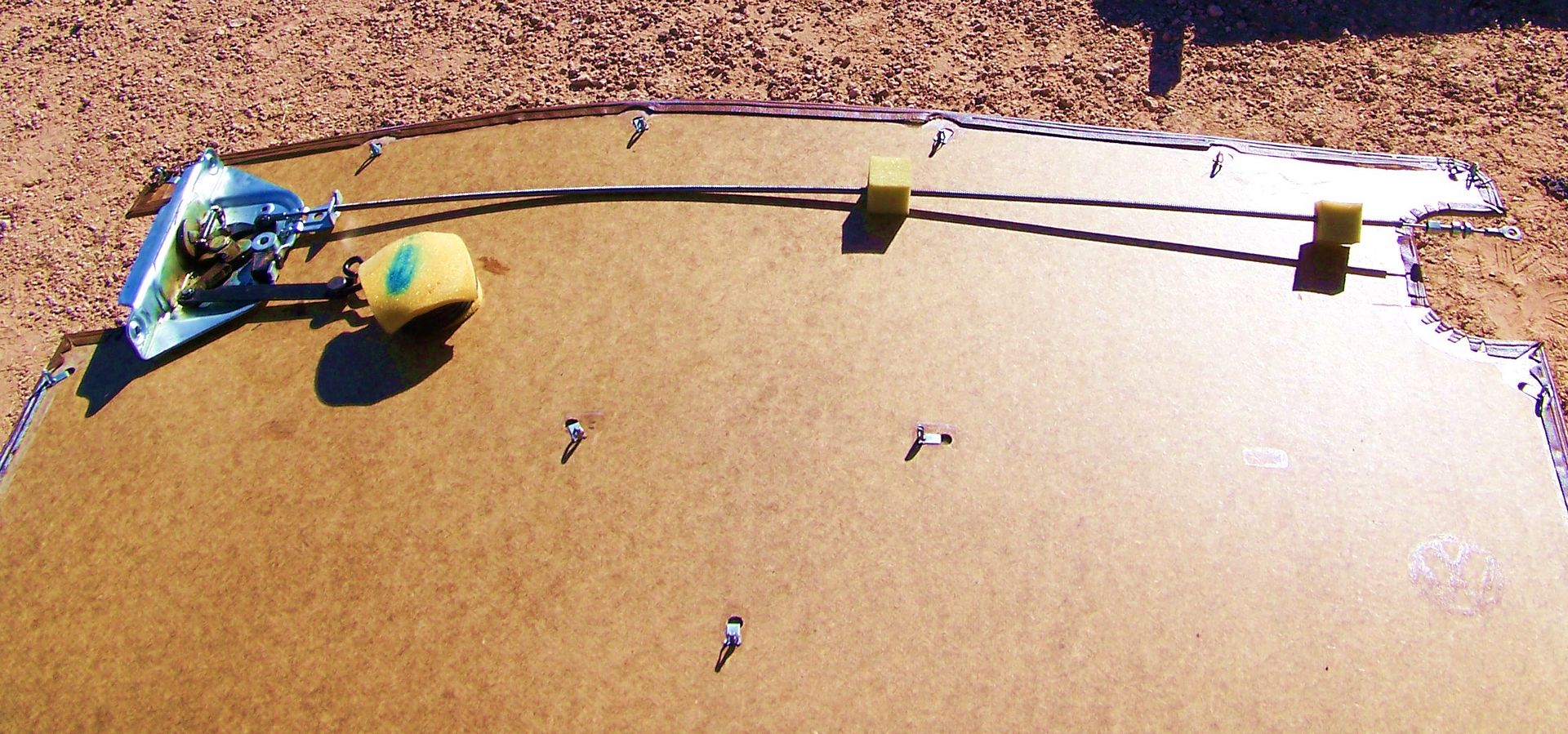
Remove C clip from cable end in front latch. Gently pull cable sheath out of plastic retainer midway. If retainer is broken, procure a wire tie for reassembly. There should be a foam block at the middle point, and at the forward third of the cable sheath. If yours are damaged or missing, cut a couple of 2" blocks out of the mattress in the guest bedroom.
Release cable end from forward latch assembly. There is a preload so don't freak if the latch actuator springs away a bit. Loosen the 10mm locknut that holds the cable sheath to the latch bracket. Do not disturb the adjustment if your door has been working correctly.
Step 3) Remove Latch Assembly From Door
Push the coiled up spring swaddled in foam towards the front of the car so you can remove the anchor rod from the sliding door inner frame. Let spring lay down slowly. Remove the cabin-facing phillips screw in the rear latch. Now open the door halfway and loosen the outer phillips screws while supporting the assembly.
Once the screws are out, you can withdraw the latch assembly and dangling spring and cable to the rear. See how simple this stuff is?
Step 4) Lubricate & Clean
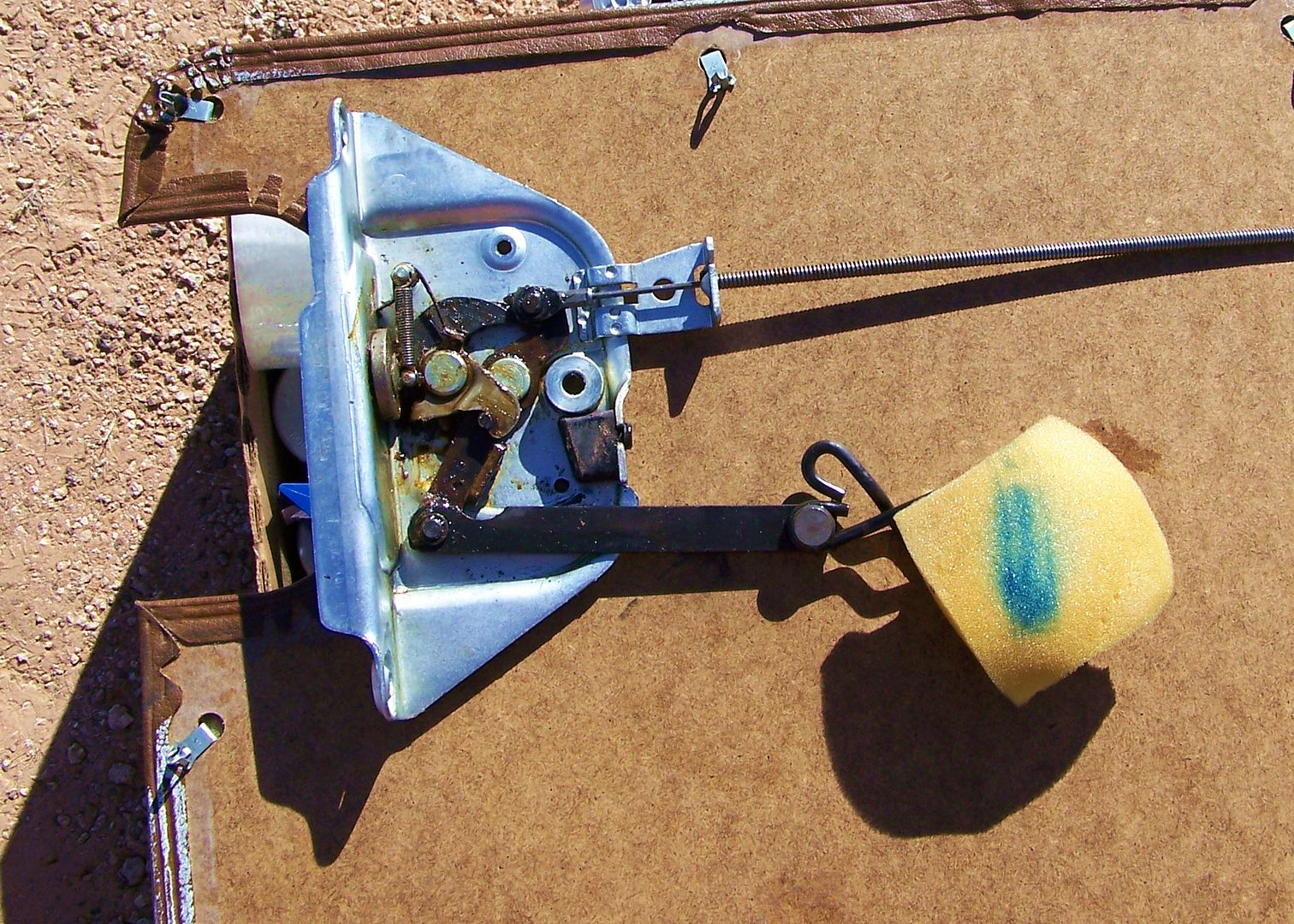
You want to reapply grease to cleaned parts, and then blast the grease into hard-to-reach areas with some aerosol like WD-40. I slathered 80-90 gear oil on the greasy mess and let it work into the actual latch as it goes through the body of the assembly, and I slowly introduced gear oil into the cable sheath so it could run down the length of the cable. Every contact point that you see wants grease, full-strength. The spring in foam on the BobD was dry, unlike most torsion springs, but I kept it dry. I assume it is to keep the foam healthy. Actuate the levers and catches and get the lubrication where it needs to go. Now wipe it down clean clean clean on all interior facing surfaces, and mop up all drips everywhere:
Step 5) Reassembly
Wax the door's paint under the latch assembly and along the perimeter where the clips go in. Do all exposed painted surfaces if you care about your bus AT ALL.
Now re-install rear latch taking care to negotiate the foam swaddled spring and cable through the skinny space between the door and the body. Start the rear screws to barely snug, go around and get the cabin facing screw started to barely snug. Completely tighten the rear screws, then the cabin screw. This rigamorale is to make sure the latch is non-stressed and aligned before clamping the door. Pull the torsion spring with the anchor rod towards the front and insert the anchor rod into the hole in the door frame.
Step 6) Detour Diasassembly
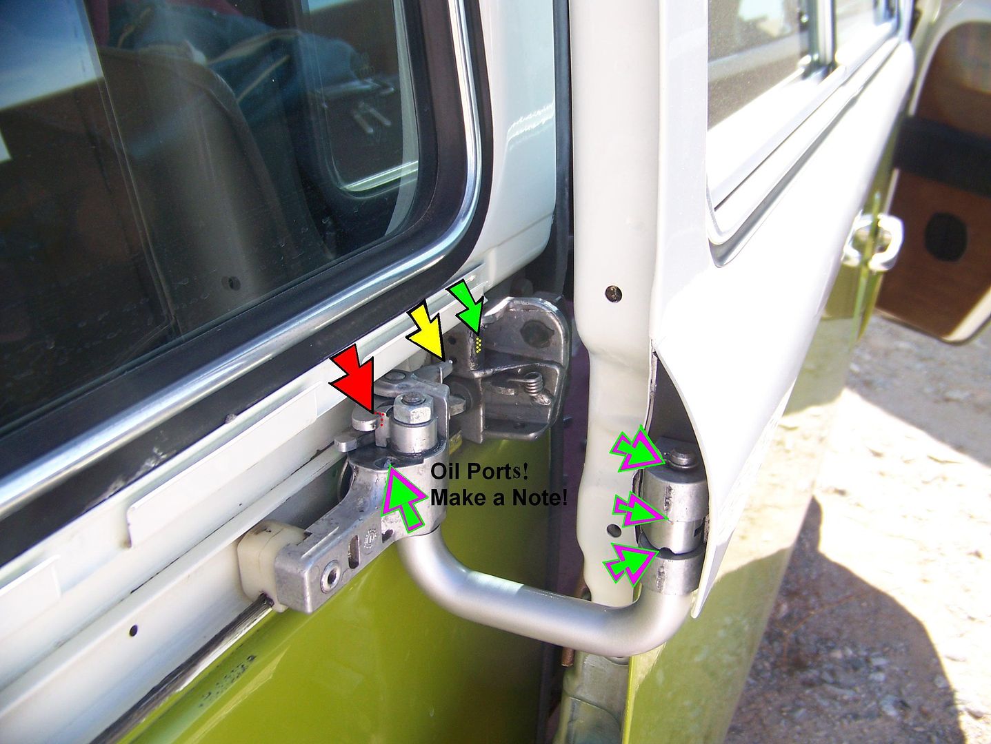
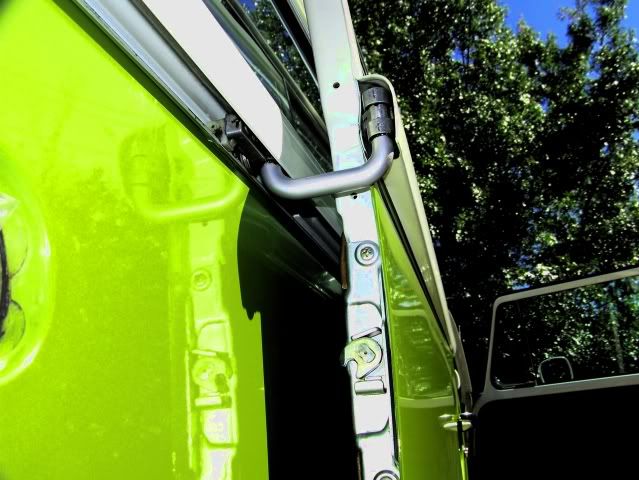
I decided to do the front latch assembly as well. There is a plastic cover with three little screws at the bottom edge of the sliding door glass that allows you to remove the three phillips screws that hold the open door catch. Then you can release the catch from the pull rod coming directly up from the front latch assembly. Remove both door handles and the outer plastic grommet. Remove three phillips screws, and lower the assembly down and out to let that pull rod get free of the door and the assembly is in your hand. Harder to lubricate this assembly with the rivets holding it together, so I did a gear oil baptism after a pathetic effort at poking grease in every available spot. Again, work the grease and oil into the works while it is in your hand at angles it will never see again.
Wipe it clean of oil/grease drool. Check that the lock cylinder is secured snugly with that single phillips screw attaching it to the body of the latch assembly. Reinsert the pull rod in the door leading up to the catch and get the latch assembly in position. Re-insert the three phillips screws that hold the assembly to the door, but do not tighten until you have the outer door handle/grommet installed, they serve to pilot the whole assembly. By the way, a Type 4 pushrod tube seal serves as an excellent replacement for the felt that is supposed to reside between the plastic grommet and the outer door handle. A half turn of electrical tape on the outer perimeter of the plastic grommet will help it seat more securely in the door opening. And a wrap of HVAC aluminum tape on the door handle shaft itself (adjust-to-fit by hacking off at 1" intervals until it slips into the grommet (use Valvoline DuraBlend grease on last insertion) will give you a nice smooth tight door handle action. Reinstall the cable sheath into the bracket, and pull lever towards cable eye until it slips on + circlip. Tighten your 10mm locknut, and place foam blocks where they will serve best to prevent rattles. If your cable is all out of adjustment, there is a little hole in the rear latch assembly where you insert a 4mm allen wrench or screw to hold the rear lever into position while taking up the slack in the cable with the adjustment turn buckle where the 10mm locknut resides. This is true for the earlier latch assemblies too, you just have to scare up more 4mm allen wrenches or screws since they use two rods, or one rod and one cable. Everything gets adjusted to just barely snuggish. The door should open at 1 3/4" movement of the handle.
Step 7) Door Panel On
Start all lower clips first. Then reach down and final-align the center clips and pop them in. Finish up, and be amazed at how light and precise these doors can be.
Colin
Did you know that the resistance you experience is actually a coiled-up spring installed precisely to give you thatr resistance? Who wudda thunk?
Step 1) Remove Door Panel.
Start at a healthy section and pull out as close to a determined clip location as possible.
Before proceeding, please re-glue the entire perimeter of the vinyl to the masonite panel. I'll wait here . . . . .
Step 2) Release Cable and Return Spring Anchor
Remove C clip from cable end in front latch. Gently pull cable sheath out of plastic retainer midway. If retainer is broken, procure a wire tie for reassembly. There should be a foam block at the middle point, and at the forward third of the cable sheath. If yours are damaged or missing, cut a couple of 2" blocks out of the mattress in the guest bedroom.
Release cable end from forward latch assembly. There is a preload so don't freak if the latch actuator springs away a bit. Loosen the 10mm locknut that holds the cable sheath to the latch bracket. Do not disturb the adjustment if your door has been working correctly.
Step 3) Remove Latch Assembly From Door
Push the coiled up spring swaddled in foam towards the front of the car so you can remove the anchor rod from the sliding door inner frame. Let spring lay down slowly. Remove the cabin-facing phillips screw in the rear latch. Now open the door halfway and loosen the outer phillips screws while supporting the assembly.
Once the screws are out, you can withdraw the latch assembly and dangling spring and cable to the rear. See how simple this stuff is?
Step 4) Lubricate & Clean
You want to reapply grease to cleaned parts, and then blast the grease into hard-to-reach areas with some aerosol like WD-40. I slathered 80-90 gear oil on the greasy mess and let it work into the actual latch as it goes through the body of the assembly, and I slowly introduced gear oil into the cable sheath so it could run down the length of the cable. Every contact point that you see wants grease, full-strength. The spring in foam on the BobD was dry, unlike most torsion springs, but I kept it dry. I assume it is to keep the foam healthy. Actuate the levers and catches and get the lubrication where it needs to go. Now wipe it down clean clean clean on all interior facing surfaces, and mop up all drips everywhere:
Step 5) Reassembly
Wax the door's paint under the latch assembly and along the perimeter where the clips go in. Do all exposed painted surfaces if you care about your bus AT ALL.
Now re-install rear latch taking care to negotiate the foam swaddled spring and cable through the skinny space between the door and the body. Start the rear screws to barely snug, go around and get the cabin facing screw started to barely snug. Completely tighten the rear screws, then the cabin screw. This rigamorale is to make sure the latch is non-stressed and aligned before clamping the door. Pull the torsion spring with the anchor rod towards the front and insert the anchor rod into the hole in the door frame.
Step 6) Detour Diasassembly
I decided to do the front latch assembly as well. There is a plastic cover with three little screws at the bottom edge of the sliding door glass that allows you to remove the three phillips screws that hold the open door catch. Then you can release the catch from the pull rod coming directly up from the front latch assembly. Remove both door handles and the outer plastic grommet. Remove three phillips screws, and lower the assembly down and out to let that pull rod get free of the door and the assembly is in your hand. Harder to lubricate this assembly with the rivets holding it together, so I did a gear oil baptism after a pathetic effort at poking grease in every available spot. Again, work the grease and oil into the works while it is in your hand at angles it will never see again.
Wipe it clean of oil/grease drool. Check that the lock cylinder is secured snugly with that single phillips screw attaching it to the body of the latch assembly. Reinsert the pull rod in the door leading up to the catch and get the latch assembly in position. Re-insert the three phillips screws that hold the assembly to the door, but do not tighten until you have the outer door handle/grommet installed, they serve to pilot the whole assembly. By the way, a Type 4 pushrod tube seal serves as an excellent replacement for the felt that is supposed to reside between the plastic grommet and the outer door handle. A half turn of electrical tape on the outer perimeter of the plastic grommet will help it seat more securely in the door opening. And a wrap of HVAC aluminum tape on the door handle shaft itself (adjust-to-fit by hacking off at 1" intervals until it slips into the grommet (use Valvoline DuraBlend grease on last insertion) will give you a nice smooth tight door handle action. Reinstall the cable sheath into the bracket, and pull lever towards cable eye until it slips on + circlip. Tighten your 10mm locknut, and place foam blocks where they will serve best to prevent rattles. If your cable is all out of adjustment, there is a little hole in the rear latch assembly where you insert a 4mm allen wrench or screw to hold the rear lever into position while taking up the slack in the cable with the adjustment turn buckle where the 10mm locknut resides. This is true for the earlier latch assemblies too, you just have to scare up more 4mm allen wrenches or screws since they use two rods, or one rod and one cable. Everything gets adjusted to just barely snuggish. The door should open at 1 3/4" movement of the handle.
Step 7) Door Panel On
Start all lower clips first. Then reach down and final-align the center clips and pop them in. Finish up, and be amazed at how light and precise these doors can be.
Colin