Setting proper rocker arm geometry.

Moderators: Sluggo, Amskeptic

Post Reply
User avatar
ruckman101
Lord God King Bwana
Location: Up next to a volcano.
Contact:
Status: Offline

Setting proper rocker arm geometry.

Post by ruckman101 » Tue Jan 14, 2014 3:58 pm

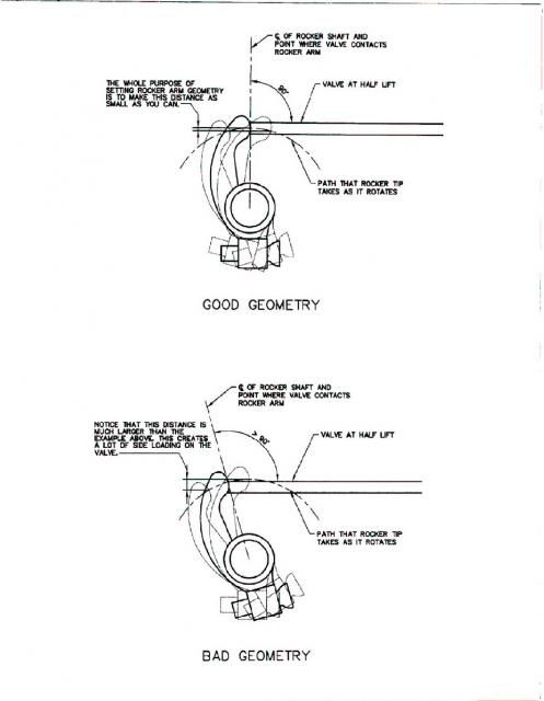
How do I do this? I understand the principle, but how do I accurately measure it?

Image

I get a measurement of .354 inches of total travel, so my rocker arm should be parallel at .177 inches, but eyeballing it seems less than accurate. I mean it looks pretty good, but ... . Striving for "just exactly perfect".


thanks,
neal
The slipper has no teeth.

User avatar
Amskeptic
IAC "Help Desk"
IAC "Help Desk"
Status: Offline

Re: Setting proper rocker arm geometry.

Post by Amskeptic » Tue Jan 14, 2014 10:07 pm

ruckman101 wrote:How do I do this? Striving for "just exactly perfect".


thanks,
neal
Relax. Eyeball it. You can *see* the arc of the screw enter into parallel with the valve stem. THEN measure exactly half lift backwards towards closed. If it is clicky, it was "not enough" at half-lift. If it is still under pressure then it was "too much" at half lift.
Colin
BobD - 78 Bus . . . 112,730 miles
Chloe - 70 bus . . . 217,593 miles
Naranja - 77 Westy . . . 142,970 miles
Pluck - 1973 Squareback . . . . . . 55,600 miles
Alexus - 91 Lexus LS400 . . . 96,675 miles

User avatar
ruckman101
Lord God King Bwana
Location: Up next to a volcano.
Contact:
Status: Offline

Re: Setting proper rocker arm geometry.

Post by ruckman101 » Tue Jan 14, 2014 11:52 pm

Clicky? You mean I shouldn't have the normal gap while making this assessment?


neal
The slipper has no teeth.

User avatar
Amskeptic
IAC "Help Desk"
IAC "Help Desk"
Status: Offline

Re: Setting proper rocker arm geometry.

Post by Amskeptic » Wed Jan 15, 2014 9:02 pm

ruckman101 wrote:Clicky? You mean I shouldn't have the normal gap while making this assessment?


neal
I do. That is where it operates. If you get rid of all clearance, the screw is further in the rocker arm. If you set the mid-lift parallel here, then back the screw off to get clearance, then your actual mid-lift is going to be applying a slight downwards pressure on the valve stem. Visualize it. You have the perfect parallel with no clearance. OK. When you subsequently adjust for .006" clearance, the screw is now *away*. The rocker arm has to travel in further to touch, then open the valve. That means you will be past parallel at mid-lift. Ergo, adjustment screw is beginning to arc downwards, valve is now spending too much time slightly downwards.
ColinYesTrigonometryWouldHelp
BobD - 78 Bus . . . 112,730 miles
Chloe - 70 bus . . . 217,593 miles
Naranja - 77 Westy . . . 142,970 miles
Pluck - 1973 Squareback . . . . . . 55,600 miles
Alexus - 91 Lexus LS400 . . . 96,675 miles

User avatar
ruckman101
Lord God King Bwana
Location: Up next to a volcano.
Contact:
Status: Offline

Re: Setting proper rocker arm geometry.

Post by ruckman101 » Sat Jan 18, 2014 2:24 pm

Okie dokie, I've given this issue another look. And I don't like it.

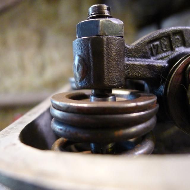
Here's the rocker arm up with valve closed.

Image

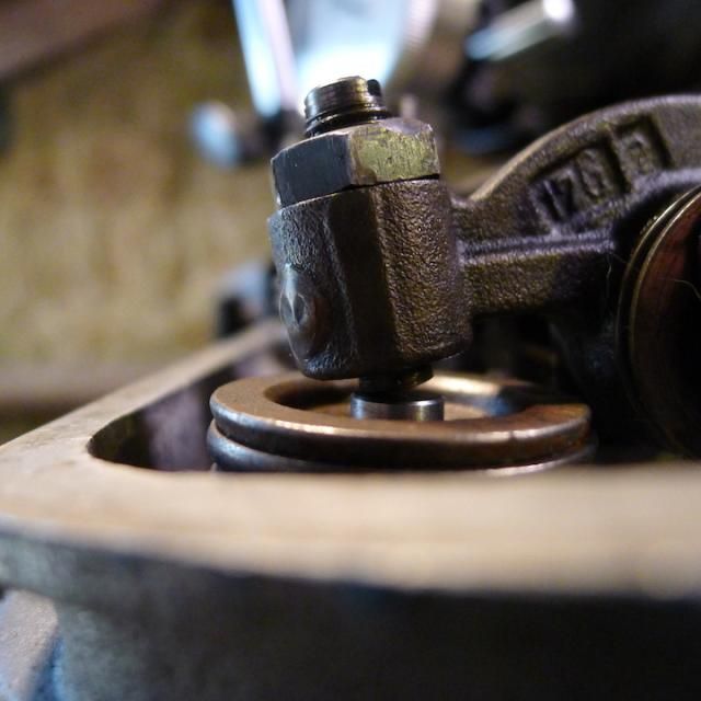
Here we are eyeballed parallel with the valve stem.

Image

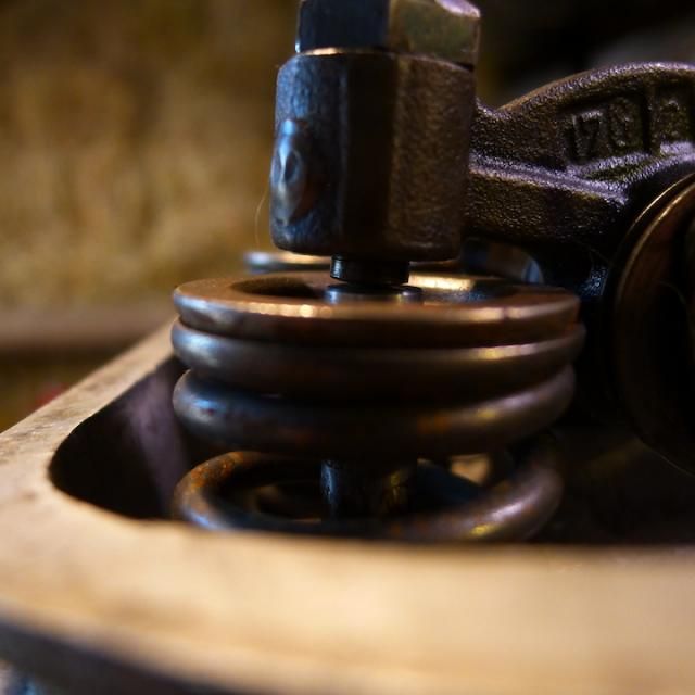
And finally fully open.

Image

Now as I understand it, I'm trying to get the rocker arm parallel with the valve stem half way through the total arc of travel of the rocker arm, which would make the angle to the valve stem roughly the same at both ends of the arc. It isn't. It looks like I need to either shorten the pedestal mounts of the rocker arm assembly, or the push rods.


neal
The slipper has no teeth.

User avatar
Xelmon
Sedna of VW lovers
Location: LA or Portland, OR
Status: Offline

Re: Setting proper rocker arm geometry.

Post by Xelmon » Mon Jan 20, 2014 12:06 pm

Now that I looked at it, I havez a better idea what you are looking at too.

Actually by the diagrams you shouldn't be looking at the valve stem. You should instead focus on the geometry instead, aka, at half open, keep the rocker 90* in relation to the push-rod.

The reason for this is to decrease motion and thus aggravated wear on the rockers and push-rods. If the gap screw goes out, it's a 1 minute job and costs peanuts. Worn-out rockers? Now that's more than a 1 minute job, and it probably would run a few hundred pounds of peanuts. =)

User avatar
ruckman101
Lord God King Bwana
Location: Up next to a volcano.
Contact:
Status: Offline

Re: Setting proper rocker arm geometry.

Post by ruckman101 » Mon Jan 20, 2014 12:10 pm

At 90 degrees the valve is perhaps a third of the way open.


neal
The slipper has no teeth.

User avatar
Amskeptic
IAC "Help Desk"
IAC "Help Desk"
Status: Offline

Re: Setting proper rocker arm geometry.

Post by Amskeptic » Mon Jan 20, 2014 12:42 pm

Xelmon wrote:Now that I looked at it, I havez a better idea what you are looking at too.

Actually, you don't, so I need to edit your post.

This is not at all about the orientation of the push rod to rocker arm.
It is solely to keep side loads on the brass/phosphur bronze valve guides to a minimum.

That means that adjusting screw needs to be applying force at as close to in-line with the stem as possible.

Ruckman101, you really are not that far off. What your geometry shows me is that the cylinder head is closer to the crankcase, due to flycut somewhere.

Amazingly, your geometry will be improved by shimming the rocker supports OUT by some .015" or perhaps .020" or more.

I believe your thinking as as follows:
You see a "shallow" initial angle
You see a "steep" fully open angle.
You think that reducing either the push rod length or the rocker support, would allow the rocker arm to operate more in the middle of the required closed valve-angle/parallel/open valve-angle.

But look at what really happens:
Let's BACK OUT the rocker support and stick a shim under it. That makes the push rods "shorter". The initial rocker angle gets more serious. The fully open rocker angle gets less serious. And (ta DA) the valve adjusting screw will end up more through the rocker arm to reassert the correct valve clearance. This will help give you more room between the rocker tip and the valve spring retainer when the eventual valve recession bugaboo crops up.

Try it. Let me know!
Colin
BobD - 78 Bus . . . 112,730 miles
Chloe - 70 bus . . . 217,593 miles
Naranja - 77 Westy . . . 142,970 miles
Pluck - 1973 Squareback . . . . . . 55,600 miles
Alexus - 91 Lexus LS400 . . . 96,675 miles

User avatar
Xelmon
Sedna of VW lovers
Location: LA or Portland, OR
Status: Offline

Re: Setting proper rocker arm geometry.

Post by Xelmon » Mon Jan 20, 2014 2:39 pm

Amskeptic wrote:
Xelmon wrote:Now that I looked at it, I havez a better idea what you are looking at too.
This is not at all about the orientation of the push rod to rocker arm.
It is solely to keep side loads on the brass/phosphur bronze valve guides to a minimum.
Oh... OOoooooohhhh, right, that makes sense! I didn't eve think of that, was still in the coffee daze of the morning.

Really, bushings are that soft? Hm, good to know.

User avatar
Amskeptic
IAC "Help Desk"
IAC "Help Desk"
Status: Offline

Re: Setting proper rocker arm geometry.

Post by Amskeptic » Mon Jan 20, 2014 9:14 pm

Xelmon wrote: Really, bushings are that soft? Hm, good to know.
"Bushings"? Belt down another coffee . . .

Valve guides have to be able to work with very little lubrication. Bronze-phosphor guides can function well in a limited lubrication environment such as a VW with valve stems that point UP! towards the combustion chambers, and better yet, bronze can conduct heat pretty well which makes the exhaust valves happy. The downside is that bronze is a tad soft in relation to steel valves. We VW people must execute due diligence here, VW heads have to work extremely hard in most every way.
Colin
BobD - 78 Bus . . . 112,730 miles
Chloe - 70 bus . . . 217,593 miles
Naranja - 77 Westy . . . 142,970 miles
Pluck - 1973 Squareback . . . . . . 55,600 miles
Alexus - 91 Lexus LS400 . . . 96,675 miles

User avatar
ruckman101
Lord God King Bwana
Location: Up next to a volcano.
Contact:
Status: Offline

Re: Setting proper rocker arm geometry.

Post by ruckman101 » Tue Jan 21, 2014 1:33 am

Oi vey.

Everything obvious isn't. Mind is grasping to grasp, information overload. Deck heights, barrel shims here on this side, not as much on that side, the reality of factory case crankshaft bore to spec plus or minus allowable tolerances not necessarily just exactly perfect to begin with the subsequent bores follow.

Oi vey.

Oh, hey, yes the rocker arm gap adjust screws do have lots of travel room. Another nervous notice, why are they so close to the rocker arm itself? And I haven't checked but the one side. Now I have to check the other side.

Oh oh oh oh, I have seen the light!! More than one angle when it comes to geometry. I got locked into less than all.

Relax. I feel much better now.


neal
The slipper has no teeth.

User avatar
Xelmon
Sedna of VW lovers
Location: LA or Portland, OR
Status: Offline

Re: Setting proper rocker arm geometry.

Post by Xelmon » Tue Jan 21, 2014 10:41 am

Amskeptic wrote:
Xelmon wrote: Really, bushings are that soft? Hm, good to know.
Valve guides have to be able to work with very little lubrication. Bronze-phosphor guides can function well in a limited lubrication environment such as a VW with valve stems that point UP! towards the combustion chambers, and better yet, bronze can conduct heat pretty well which makes the exhaust valves happy. The downside is that bronze is a tad soft in relation to steel valves. We VW people must execute due diligence here, VW heads have to work extremely hard in most every way.
Colin
... Did I seriously misread that that badly? Seems like it, yesterday was a bit of a madhouse and a twiddling thumbs kind of day all in one.

User avatar
ruckman101
Lord God King Bwana
Location: Up next to a volcano.
Contact:
Status: Offline

Re: Setting proper rocker arm geometry.

Post by ruckman101 » Wed Jan 22, 2014 4:00 pm

Well, stuck a washer in there to raise the rocker arm assembly out. Re-adjusted the gap, and much better. Washer measured at 1.005 mm, or basically .040 inches. Looks much better. Somehow I have it in my mind that washers are a no-no. Proper shims come in .015, .030, and .060 inches. I will get some new photos up soon.


neal
The slipper has no teeth.

Post Reply